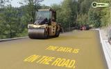
The Trimble dimensions event in Las Vegas provided an oppurtunity for demonstrations and training with the firms latest 3D PCS900 paving package
Milling and paving repair operations for airport runways require particularly high tolerances, an obvious market for 3D control solutions writes Mike Woof
Airport runways require some of the most accurate quality standards and tightest tolerances of any asphalt or concrete surface. This is one area where the high precision capabilities of 3D systems offer clear advantages.At the
Although Western Rock had experience of using
Using the 3D system did provide a learning curve for Western Rock and Buoy said that the firm had previously used conventional methods requiring placing, g rading and maintaining string lines to guide the milling and paving processes. However he said, "By using 3D we were able to eliminate time and money setting out the piano wire for the bottom and top lift." The time savings were of benefit and Buoy continued, "We had a tight timetable to get the paving done as they'd had delays elsewhere in the project. The Trimble system really helped by cutting out the surveying and setting out times. The good thing about this system is that it's very user friendly and very easy to control and manage." The PCS900 system was used to control the grade and slope of the screed to a 3D design, with signals from a universal SPS930 total station.
The location of the total stations was leapfrogged along either side of the runway stretch every 152m. Since then the firm's sister company has used the Trimble technology on road projects, placing the total stations a similar distance apart but on the same side of the roadway. Buoy explained that the vibration generated by working machines (and compaction equipment in particular) provides an important reason to keep the total stations some distance from the job-site and he added, "A thing you've got to watch is that the station doesn't get knocked over." The equipment was fitted to a
Key as-built data for Western Rock's contract included the base surface, the design to be paved and the asphalt compaction factor. Grade checking was carried out before compaction and again afterwards, "To check we met the design," Buoy said.
The job was not straightforward and moving the crown of the runway by 7.62m posed a challenge as this required moving a good deal of material. Employing the 3D package reduced overall material usage by around 3%, a notable benefit for Western Rock. And Buoy commented, "Using 3D paving changes the way the contractor works. You reduce grinding costs and reduce asphalt use." The quality of the work and speed of construction showed Western Rock that its investment in the Trimble 3D was sound as the firm met its tolerances and easily finished the contract within the tight time frame, despite being a new user of the technology.
Also in the US, sophisticated 3D milling and paving control technology from Trimble has been used in another airport runway improvement job. The Hot Springs Runway repair project in Arkansas has been handled by the
This small airport handles mainly general aviation and has two asphalt runways, with Runway 13-31 having had to be repaved. Brian Tinnel of Redstone Construction also attended Trimble Dimensions and explained that his firm used a range of Trimble equipment for the project including four SPS 930 Robotic Total Stations and two TSC2 data collectors equipped with the latest SCS900 control package. Both 2D and 3D systems were employed for the work on two sections of the airport, one measuring 319x23m and the other 792.5x30.5m. The work also included moving the crown of the runway from around 7.62m away from the centreline to the actual centreline, so as to improve water run-off and general safety.
The finished grade model was built by using point files directly from the cross sections in the plans. The finished grade model was also dropped 25.4mm to create a subgrade surface and this was then used to calculate the daylight line between milling area and paving area. The areas were then marked and level-up was completed prior to milling, which was carried out using a
The Area 1 section was paved by using a joint match along the existing edge and 3D Elevation from the model on the first two passes at 3.81m for each pass. The next three passes at 5.08m each were paved by joint match along the hot mat and 3D slope from the model. The Area 2 section was paved using full 3D capabilities on the first two passes (10-15.24m to the left and from the centreline to 5.2m to the right). The next two passes were made in tandem with the Caterpillar AP1055 running a joint match and 3D slope from the model and the Caterpillar AP655 running the joint match on both sides while using a 2D Trimble PCS400 system to tie in with a cold joint on one side and a hot joint on the other (from the centreline to 10m to the left and from 5.2-15.24m on the right).
The grade was checked during the paving phase from the uncompacted mat and a finished surface, as-built check was carried out after all the paving work was completed.
A P-401 asphalt overlay was used and the surface was measured using a profilograph to ensure the work met the required finished grade tolerances. The results of the checks showed that the milled and repaved sections passed the profilograph, straightedge and grade tolerance requirements with zero dips or grinds.


